Smart Home Physical Infrastructure
While there are various technical layouts and configurations available for modern home automation, this project proposes a specific, highly optimized physical infrastructure design. This proposed architecture focuses on the direct integration of balanced heat recovery ventilation, solar thermal harvesting, backup combustion heating, direct hydronic space heating, motorized active shading, and multi-split air conditioning to achieve superior thermal efficiency and indoor comfort.
Individually, each of these technical elements is fully capable of operating as a standalone system. However, they are not natively designed to interact or communicate with one another. The core objective of this project is to bridge these gaps, establishing a perfect operational harmony by integrating all isolated components into a single, unified smart system.
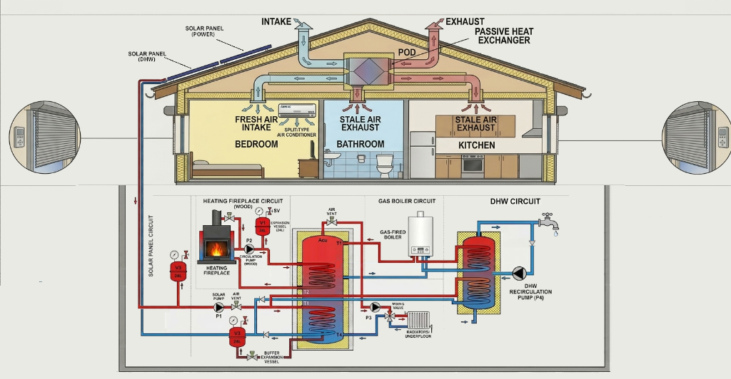
Figure 1.1: Complete mechanical, thermal, and passive shading integration layout (Click to expand).
The building's energy and air circulation mechanics are divided into three primary, tightly integrated subsystem loops:
1. Controlled Heat Recovery Ventilation
Ensures optimal indoor air quality across all 3 floors of the residence without losing precious thermal energy. The system is designed to balance relative humidity, remove indoor air pollutants (such as CO₂ and VOCs), and recover up to 85% of thermal energy.
Fresh Air Supply (Living & Sleep Zones)
Oxygen-rich, filtered, and pre-heated fresh air is continuously introduced into all dry living areas across the three floors:
- 3 Bedrooms (Upper Floor): Guaranteed steady fresh air supply overnight for deep sleep and stable CO₂ levels.
- Living Room, Dining Area & Game Room (Ground Floor): High-volume fresh air distribution to active family zones.
- Office (Basement): Dedicated fresh air exchange to maintain alertness during long hours of work or study.
Stale Air Extraction (Wet & Tech Zones)
Humid, stale, or odor-prone air is continuously extracted from utility and wet areas across the levels to maintain balanced air pressure:
- 3 Bathrooms (Distributed All Floors): Rapidly removes moisture and steam, preventing condensation, mold, and humidity damage.
- Kitchen (Ground Floor): Direct extraction of cooking-related smells and moisture, working in tandem with the stove hood.
- Technical Room (Basement): Removes heat generated by servers, power supplies, and central boiler pumps.
2. Thermal Harvesting & Active Cooling
A diversified model guarantees redundancy, cost-efficient carbon-neutral heating, and active summer cooling:
- Solar Thermal Loop: Roof-mounted solar collectors harvest thermal radiation. Managed by solar pump P1, a central air vent, and expansion vessel V3, distributing heat directly to the Domestic Hot Water (DHW) cylinder or space heating manifolds.
- Wood-Burning Fireplace Loop: High-temperature wood-burning insert equipped with a hydronic water jacket. Operates at high pressure with circulation pump P2, expansion vessel V1, and safety valve (SV), supplying heat directly to the main heating circuit manifolds.
- Gas Boiler Loop: A high-efficiency gas-fired boiler serves as the primary automated backup, managed by circulation pump P3 and a mixing valve to top up heat demands instantly.
- Air Conditioning (Active Cooling): During hot summer periods, multi-split air conditioning systems are utilized across living zones (living room, office, game room) and the 3 bedrooms to deliver rapid active cooling, thermal comfort, and localized dehumidification.
3. Thermal Distribution & Shading
Thermal energy is directed to terminal outputs and managed passively via physical barrier integration:
- Underfloor Heating Only: Highly efficient underfloor heating is installed exclusively across all three floors of the residence (no radiators). Warm water is distributed via central manifolds, using a smart mixing valve to modulate water supply temperature according to the outdoor weather curve.
- Domestic Hot Water (DHW): Fresh tap water is heated instantly through a separate DHW cylinder, backed by a DHW recirculating pump (P4) to maintain instant hot water delivery at taps across the 3 bathrooms and kitchen.
- Active Shading (Window Blinds): Motorized external roller shutters on bedroom and kitchen windows manage passive solar heat gain, blocking direct sunlight during hot summer periods and trapping warmth in winter.
Smart Home Software Architecture
While each hardware component and mechanical loop in our smart home is fully capable of running independently, they operate in silos without any native cross-communication. The software architecture acts as the nervous system, orchestrating and harmonizing these isolated subsystems into a single, cohesive unit.
To achieve absolute reliability and low latency, we employ a decoupled, event-driven architecture structured across three key logical layers:

Figure 1.2: End-to-end system architecture: from physical sensors to MQTT message bus and central coordination layers (Click to expand).